UFOCapture Night Sky Observation Guide V2.0


4. Post processing
4.1 Object Analysis
Step 20 Installation of UFOAnalyzer
- Download UFOAxxx.zip
- Unzip UFOAxxx.zip and get UFOA directory.
- Place UFOA directory under the UFO directory which was created at Step 5-1
- If it is version up installation, overwrite old UFOA directory by new one, so that all settings will be maintained.
- You can make multiple UFOA directories in one system, so that different setting can be selected.
- You must use the same version of UFOA in this case.
- Execute "regsvr.bat" in UFOA directory. This batch file register the location of UFOA modules to your system.
- If you change the location of UFOA directory, execute "regsvr.bat" again.
- "regsvr.bat" can be execute multiple times without any bad effect.
Step 21 Profile setting
Profile setting is the most important and most difficult step. You should set your observation conditions as correct as possible to get most accurate results.
To set parameters, you need at least one fine and clear night's observation results of UFOCaptureV2 including *.xml *M.bmp and *P.jpg or *P.bmp.
You are recommended to use clips that contains famous fixed star or constellation , because you must know the direction of camera by degrees. And the elevation of camera is recommend to be medium, because it is very difficult to distinguish direction error or rotation error around zenith.
All parameters effects each other. There is no straight way. Try and error is needed. Do not change many parameters at once or you will be in chaos. Most of the parameters depend on camera and lens, so advice from someone who uses same equipments will be great help.
Once you have decided your profile parameter, you can use same parameter as long as you use same equipments and direction.
Profile parameters are below.
- Fixed parameters
- Location (These parameters need not to change unless you change your location and system)
- Longitude
- Plus value means east, minus means west, decimal small number of deg (Not minutes seconds).
- Should be set with 0.0001 degree accuracy.
- Latitude
- Plus value means north, minus means south, decimal small number of deg (Not minutes seconds).
- Should be set with 0.0001 degree accuracy.
- Altitude
- in meter. (not used in V0.xx)
- TimeZone
- hour (you should set 0 if you operate UFOCaptureV2 in UTC mode)
- LocationID
- Identification among your group which you exchange data within.
- Less than 8 A/N is recommended, because it will be a part of file names.
- CameraID
- Identification of the observing system.
- If you have only one system, then use "_M1" or "_C1" as CameraID.
- Parameters which should be tuned using Star Map function of UFOAnalyzer
- Direction (These parameters should be set every time you change the direction of your camera)
- Direction (Center direction of FOV)
- South = 0.0 west=90.0 north=180.0 east=270.0
- Decimal small number of degree.
- Initially, you should have at least 1/10 of FOV size (5 degree for 60 degree FOV-H) of accuracy, otherwise you cannot find fixed star correspondency.
- Altitude (Center elevation of FOV)
- Ground = 0.0 Zenith=90.0
- Decimal small number of degree.
- Initially, you should have at least 1/10 of FOV size (4 degree for 40 degree FOV-V) of accuracy, otherwise you cannot find fixed star correspondency.
- Rot
- Rotation around the center of your FOV.
- Decimal small number of degree.
- You can set 0.0 when your camera is leveled.
- FOV(Field of view of your system)
- H
- Horizontal view size
- Decimal small number of degree.
- Use catalog data of your camera and lens at first (ex 60.0deg for 1/2"CCD with 6mm lens)
- V
- Vertical view size
- Decimal small number of degree.
- You can set this parameter automatically using up-down spin control of H.
- X/Y ratio
- Ratio between the horizontal and vertical length of one pixel.
- This parameter depends on the relation between aspect ratio of your camera and capture resolution. You should tune this parameter precisely at least one.You need not to change it unless you change your camera ,capture equipment or resolution.
- Be aware that there is always some timing error between camera and capture boards.
- You should begin with 1.0 when pixel is nearly true square (NTSC-analog capture 4:3 and 640x480).
- When use 4:3 aspect ratio and the capture resolution is 720x480 (NTSC-IEEE1394) then begin with 0.889 (4*480/(3*720)).
- When use 4:3 aspect ratio and the capture resolution is 720x576 (PAL-IEEE1394) then begin with 1.067 (4*576/(3*720)).
- Distortion parameters
- Lens k2,k3
- Lens distortion parameter which modifies the distance from the center of the FOV to each pixel.
- R= k3* r^3 + k2*r^2 + (1-k2-k3)r, where r is ideal length(center=0.0, horizontal edge=1.0), and R is actual length.
- Begin with 0.0 for k2 and k3 at first.
- Wide lens usually has big distortion such as k3=0.05 and k2=-0.01.
- Narrow lens usually has very small distortion, so you may use k2=k3=0.0
- Center offset x,y
- Lens alignment error pixels. (Distance from light center and CCD center)
- CCD setting position error of 0.1mm cause 10 pixels or more errors. This parameter depends on you camera .
- You should begin tuning with x=0,y=0.
- 10 to 30 pixels of error are normal.
Step 21-1 (initial setting)
- Set appropriate directory which contains capture results such as *M.bmp, *.xml, *P.jpg/bmp as In Dir in Main sheet.
- Open Profile sheet.
- Set location parameters (Longitude, Latitude,TZ) as precise as possible.
- Set other parameters to its initial value mentioned before.
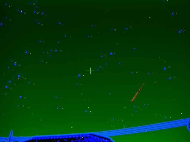
- Push Star Map button and you may see an tuning image like below.
- The blue circles shows the position of starts in input signal and yellow dot shows the position of fixed stars in star map.
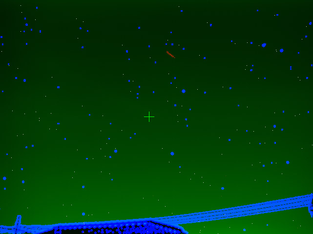
- Tune Display Mag number in Profile sheet to get appropriate number of yellow dots.
- Recognize the correspondence between blue circles and yellow dots.
- If you cannot recognize the correspondence, direction parameters or FOV parameters might be too far from actual. Do not proceed to next step, correct it first.
Step 21-2 (rough setting FOV)
- Tune direction parameters(Direction, Altitude, Rot) as precisely as possible toward the state that yellow dots come just on blue circle.
- Look at a star which is near right edge center altitude, and tune H by spin button to the state that horizontal size is matched.
- Tune X/Yratio to the state that vertical size is matched,
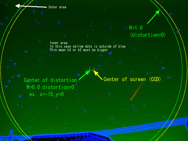
Step 21-3 (rough setting of distortion)
- Set Center offset x,y to get the state that yellow and blue have same relation around the distortion center (green cross mark).
- Look carefully the distance between yellow and blue of all position in screen, and estimate the position of distortion center.
- For example, when distortion appears bigger in left half, the center must be more left.
- You should tune direction parameters simultaneously to get appropriate center direction , altitude, rotation when you change center offsets.
- The figure below shows an example of almost correct setting of Center offset x,y.
- Yellow and blue meets both R=0.0 and R=1.0
- Relation between yellow and blue is same around the center.
- Tune Lens k3 to get the state that yellow and blue match in outer area (R>1.0).
- When yellow comes inside of blue at the outer area, you should increase k2.
- Tune Lens k2 to get the state that yellow and blue match in inner area(R<1.0).
- Tune k3 and k2 to get the minimum errors on all screen.
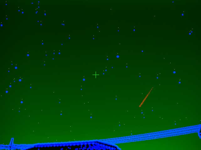
Step 21-4 (fine tuning)
- Repeat Step 21-2 to 21-3 to get satisfying matching.
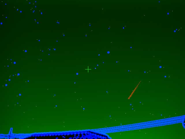
- The figure below shows samples of the effect of each parameter. You should know which parameter effect how.
| This is a sample of successful tuning result.
All star image(blue circle) are match to reference star which are calculated from star map data(yellow dot).
You can tune number of reference stars by changing Display Mag .
There are still stand alone blue circles. They may be dim star, planets, hot spot of CCD, clouds or ground objects.
|
 |
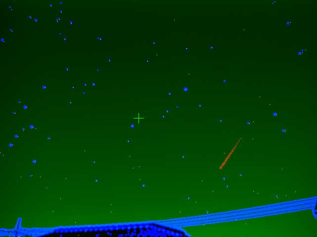
| This sample show the case when Altitude(G0) is a bit small.
All blue circles are equally below the yellow dots.
This means actual FOV was a little above the Altitude data.
|
 |
| This sample show the case when Direction(S0) is a bit small ( this is northern view).
All blue circles are equally a bit left of yellow dots.
This means actual FOV was a little right of the Direction data.
|
 |
| This sample show the case when Rot(deg) is a bit small.
All blue circles are equally rotated from the yellow dots.
This means actual FOV was a little rotated.
|
 |
| This sample show the case when FOV H&V(deg) is a bit small.
All blue circles comes a bit inside of yellow dots.
This means actual FOV was a little larger.
|
 |
| This sample show the case when FOV V(deg) is fair but H is a bit large.
Horizontally, all blue circles comes a bit inside of yellow dots. But vertical positions are fair.
These phenomena happened when the captured pixel was not true square.
In this case a pixel has a bit shorter horizontal edge than vertical edge.
Do not tune FOV H, but Set X/Yratio a bit smaller than it is.
|
 |
| This sample show the opposite case of previous one. This sample shows when only FOV H is a bit large.
Horizontally, all blue circles comes a bit outside of yellow dots. But vertical positions are fair.
In this case a pixel has a bit longer horizontal edge than vertical edge.
Do not tune FOV H or V, but Set X/Yratio a bit larger than it is.
|
 |
| This sample shows the case when Lens k2 is too small.
Blue and yellow meets near edge of the FOV, but blue come equally inside in the center area of FOV.
Try increase Lens k2 a bit.
The position of yellow dots are calculated by the equation of
R = k3*r*r*r + k2*r*r + (1-k3-k2)r
where r is the distance from the optical center position, and R is compensated distance from the optical center position to the star position.
|
 |
| This sample shows the case when Lens k3 is too small.
Blue and yellow meets near edge of the FOV, but blue come inside.
The difference becomes smaller when the star is near the center.
Try increase Lens k3 a bit.
|
 |
| This sample shows the case when the true optical center position is a bit right .
Compensation of k2 and k3 differs its effect between left half and right half.
Try increase center offset x a bit .
|
 |
| This sample shows the case when the true optical center position is a bit low .
Compensation of k2 and k3 differs its effect between upper half and lower half.
Try increase center offset y a bit .
|
 |
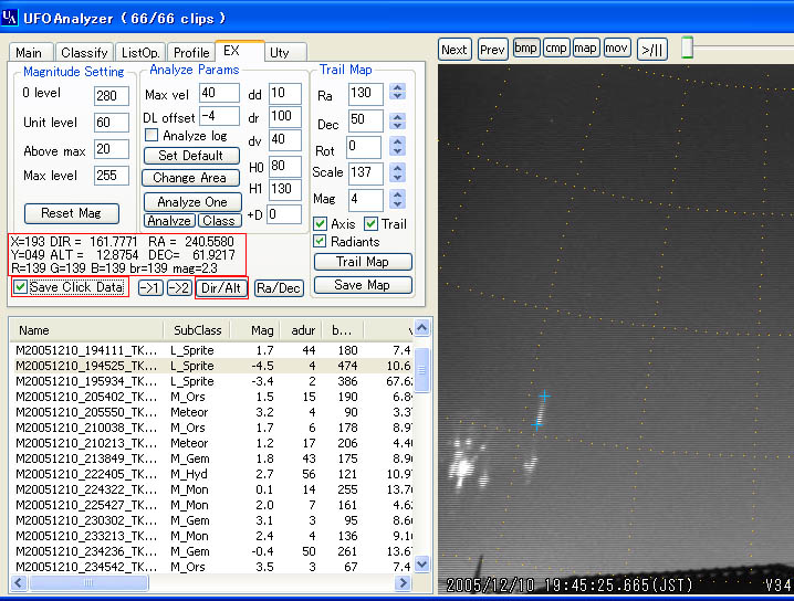
Step 22 Manual measurement
You can measure the direction and altitude of every pixel manually when profile setting has been done.
- Open EX sheet.
- In EX sheet, you can see the information of one pixel which is at the mouse cursor in view area.
- Push Dir/Alt button to display scale of direction and altitude.
- When Save Click Data check box is on, the information of clicked pixel will be save to a text file in Our dir.